forked from forks/qmk_firmware
| .. | ||
| ansi | ||
| iso | ||
| keymaps | ||
| config.h | ||
| halconf.h | ||
| info.json | ||
| leds.c | ||
| leds.h | ||
| matrix.c | ||
| mcuconf.h | ||
| post_rules.mk | ||
| raise.c | ||
| raise.h | ||
| readme.md | ||
| rules.mk | ||
| wire-protocol-constants.h | ||
Raise
- Keyboard Maintainer: ibash
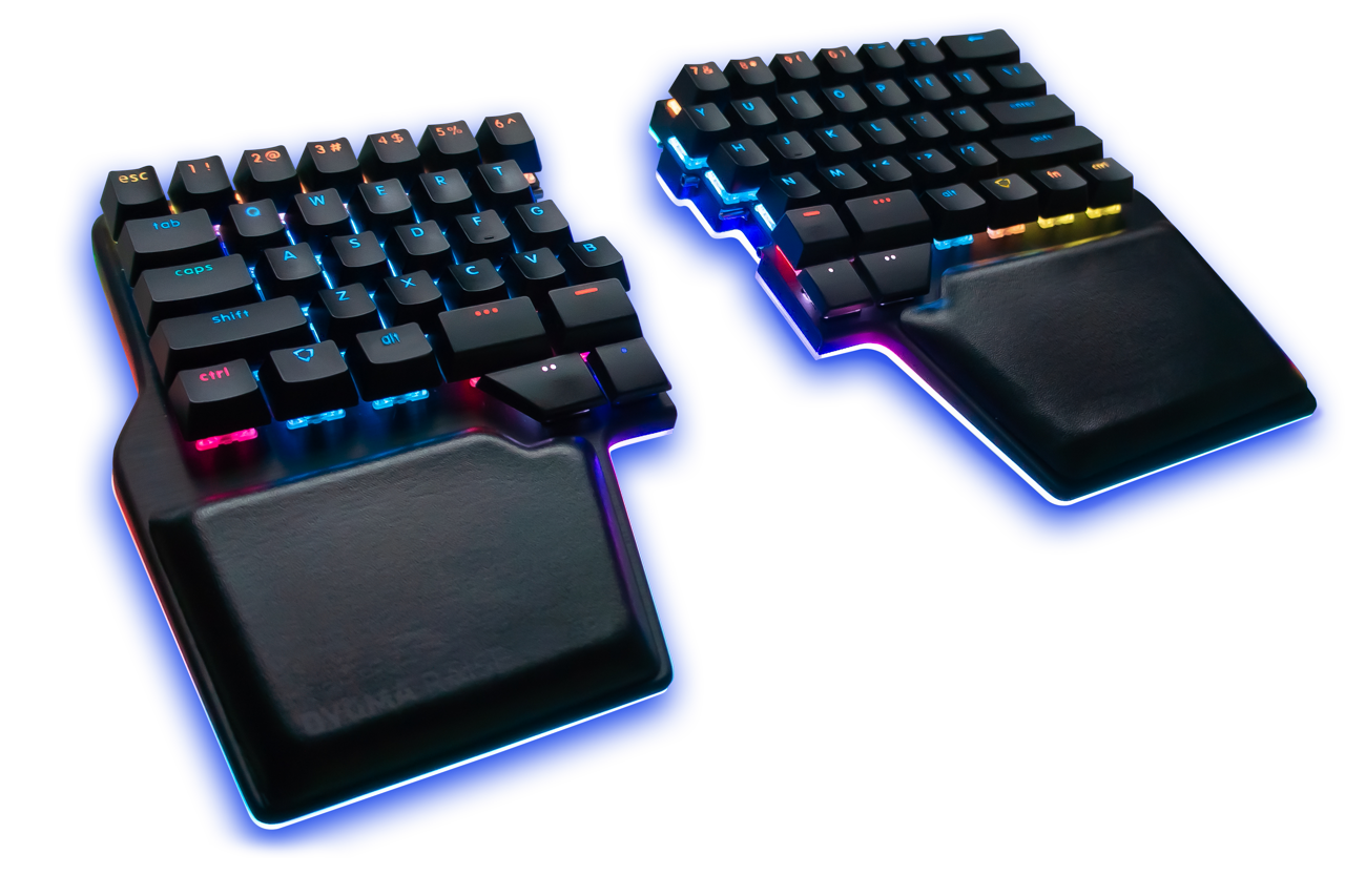
- Hardware Supported: F411 Blackpill with the Dygma Raise
- Hardware Availability: See below
Make example for this keyboard (after setting up your build environment):
make handwired/dygma/raise/ansi:default
Flashing example for this keyboard:
make handwired/dygma/raise/ansi:default:flash
See the build environment setup and the make instructions for more information. Brand new to QMK? Start with our Complete Newbs Guide.
Hardware
QMK does not currently support the Dygma Neuron because QMK does not support SAMD21 which the Neuron has. Instead this code uses a STM32 Blackpill to create a Neuron replacement.
Required Hardware
-
STM32 Blackpill from WeAct Studio (via aliexpress or adafruit).
-
2x 2.7KΩ resistors (via digikey).
-
Breadboard or PCB proto board, wires, solder, etc.
Wiring
Briefly each raise hand uses I2C to communicate with the Neuron:
- USB D+ is the I2C clock line.
- USB D- is the I2C data line.
- The resistors are pullup resistors for the I2C lines.
- Each hand draws power from the USB port.


We are also prototyping a custom pcb.


